|
|||||||||||||||||||||||||||||||||||||||||||||||||||||||||||||||||||||||||||||||||||||||||||||||||||||||||||||||||||||||
|
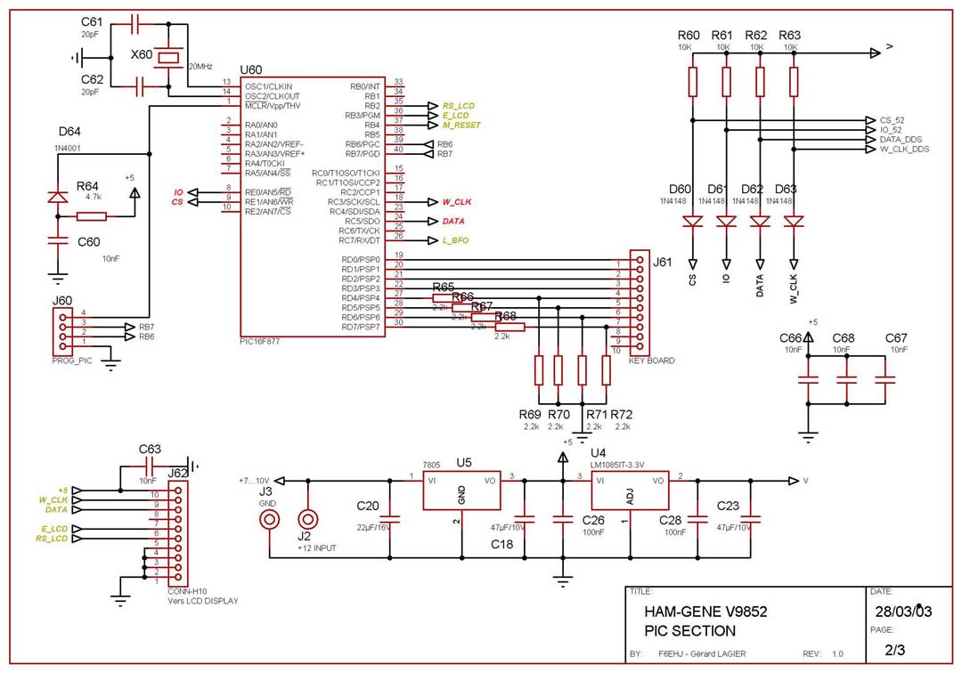
RF GENERATOR - PIC SECTION The PIC section uses a Microchip 16F877 running at 20 MHz. A frequency of 4 MHz is usually sufficient for this application. A 16 pad keyboard is used to generate the different functions : - Increase/Decrease the band number - Increase/Decrease the output frequency - Increase/Decrease the frequency step - Increase/Decrease the output level So, only 8 pads are used. The keyboard is connected to the D port. The AD9852 DDS is configurated in serial mode. So, the SPI function of the PIC is used for this purpose. SDO et SCK ouput are respectively forwarded to DATA and SCLOCK inputs of the DDS. The other wires needed for the DDS are CS (chip select) and IO Reset. These wires come from the E port of the PIC. The 2X16 LCD display allows the frequency display and the current frequency step. It shares the DATA and SCLOCk with the PIC. Two additionnal lines E and RS are required and come from B port. Provision have been made to program the PIC in-situ through connector J60. The power supply is quite simple and uses a 5volt regulator followed by a 3.3V one. If +12V is used to power the regulators, a heat dissipator on the 5V chip is recommended, considering the current drawn by the DDS (400 mA). Source code for the PIC 16F877 (Microchip ASM) HEX file for the PIC The files can be downloaded with a right click... The comments are now in english. Gérard/F6EHJ
|